Transformers Circuit Diagram
Transformer circuit meaning definition voltage globe contents Basic equations and applications of single phase transformer Transformer ideal current electrical secondary power action load impedance coil ac working arises emf tesla
Transformer Working Principle | How Transformer Works | Electrical Academia
Transformer wye phasor connections wiring diagrams connection relay electricalacademia Simple transformer winding tester circuit Parts of a power transformer
Transformer circuit equivalent diagram phase single winding primary resistance where
14+ current transformer circuit diagramIdeal transformer equations Transformer spacoWhat is an ideal transformer?.
What is a transformer?Transformer phase single parts step basic transformers electrical power current magnetic applications currents voltage cause lower does why field electronics Transformer ideal principle diagram circuit phasor winding secondary primary write figure flux their voltage twoTransformer circuit electronics electrical basics braza jenn diy posted device.

Current transformer (ct)
Ideal transformer circuit diagramTransformer working principle Transformer current diagram circuit ct working principle construction symbol operatingWhat is an ideal transformer? circuit and phasor diagram.
Transformer grounding 120v 480v 240v isolation connections technicalTransformer circuit winding tester test homemade diagram simple circuits Transformer electrical trafo relay buchholz hv owlcation kva insulation immersed bushing lv internal conservatoryTransformer equivalent phasor referred secondary parameters transformers equations determination emf induced electricalacademia.

Transformers artwork
Three phase transformer connections480v to 120v 240v transformer wiring diagram Diagram transformer wiring transformers circuit primary electric secondary coil step voltage core down iron simple basic utexas farside lectures phIdeal equations losses.
Transformers microcontroller artwork waveforms generated axon pwm were boardHow transformers work Transformer circuit working principle works electrical gif fig each electricalacademiaIdeal transformer in detail with schematics and equations.

Equivalent circuit diagram of single phase transformer
Transformer wiring transformers academia electricalacademiaIdeal transformer circuit diagram Difference between current transformer and potential transformer.
.


Ideal transformer circuit diagram | Download Scientific Diagram

Basic Equations and Applications of Single Phase Transformer

Ideal Transformer Equations - Tessshebaylo
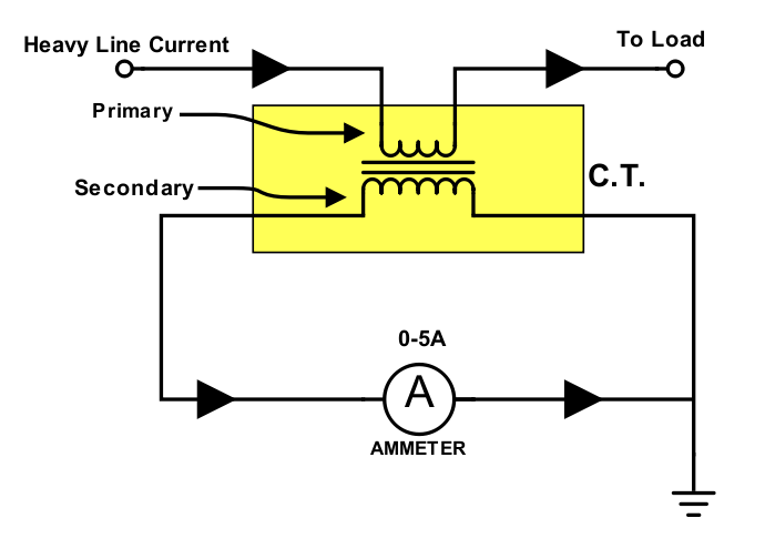
Current Transformer (CT) - Construction and Working Principle

Parts of a Power Transformer - Owlcation

Equivalent Circuit diagram of single phase Transformer

Transformers artwork

Difference between Current Transformer and Potential Transformer